Tiva ™ TM4C123GH6ZRB Microcontroller [phần 2]
Table of contents
- Tiva ™ TM4C123GH6ZRB Microcontroller [phần 2]
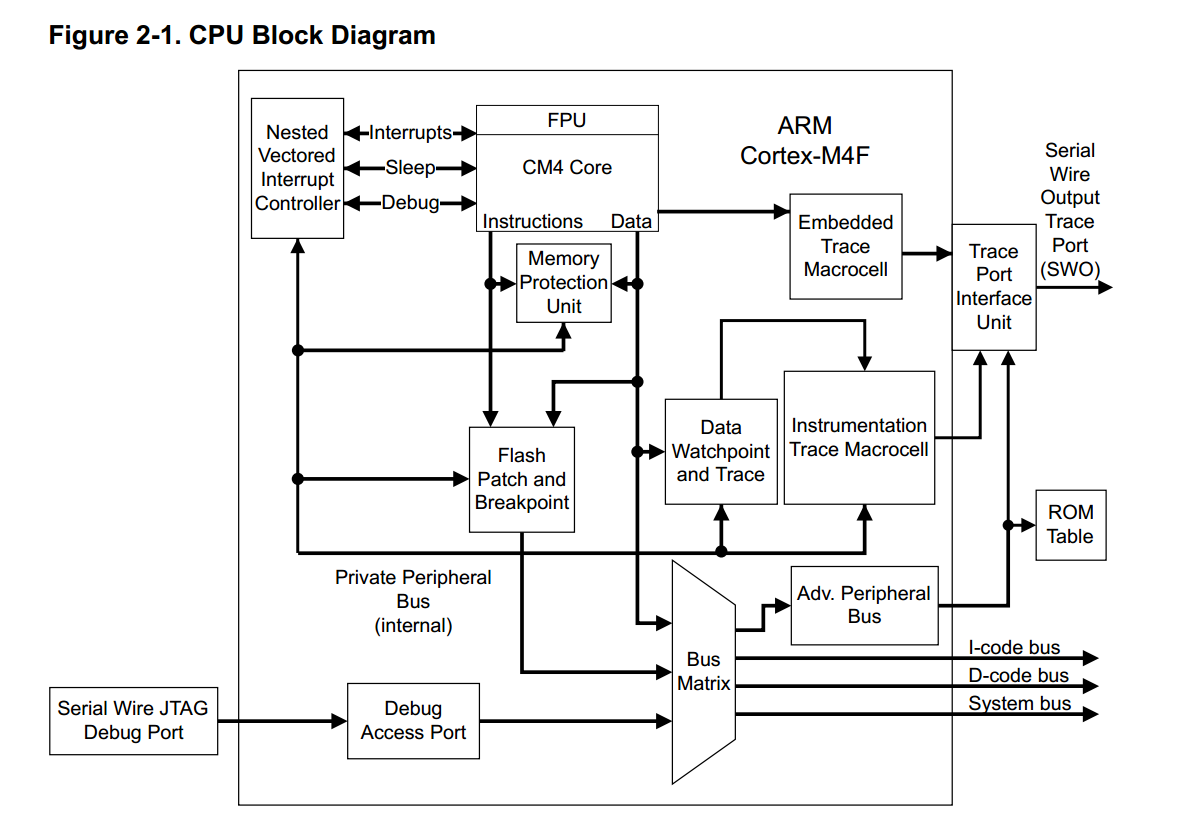
Block Diagram
- 3-stage pipeline Harvard architecture
Programming Model
Processor Mode and Privilege Levels for Software Execution
The Cortex-M4F has two modes of operation:
- Thread mode : Used to execute application software. The processor enters Thread mode when it comes out of reset.
- Handler Mode: Used to handle exceptions. When the processor has finished exception processing, it returns to Thread mode.
the Cortex-M4F has two privilege levels:
-
Unprivileged:
- Limited access to the MSR and MRS instructions and no use of the CPS instruction
- No access to the system timer, NVIC, or system control block
- Possibly restricted access to memory or peripherals
-
Privileged: software can use all the instructions and has access to all resources.
In Thread mode, the CONTROL register (see page 89) controls whether software execution is privileged or unprivileged. In Handler mode, software execution is always privileged
Only privileged software can write to the CONTROL register to change the privilege level for software execution in Thread mode. Unprivileged software can use the SVC instruction to make a supervisor call to transfer control to privileged software
Stacks
The processor uses a full descending stack, meaning that the stack pointer indicates the last stacked item on the memory.
When the processor pushes a new item onto the stack, it decrements the stack pointer and then writes the item to the new memory location.
The processor implements two stacks: the main stack and the process stack, with a pointer for each held in independent registers (see the SP register on page 79).
In Thread mode, the CONTROL register (see page 89) controls whether the processor uses the main stack or the process stack. In Handler mode, the processor always uses the main stack. The options for processor operations are shown in Table 2-1 on page 75.
| Processor Mode | Use | Privilege Level | Stack Used |
|---|---|---|---|
| Thread | Applications | Privileged or unprivileged | Main stack or process stack |
| Handler | Exception handlers | Always privileged | Main stack |
Register Map
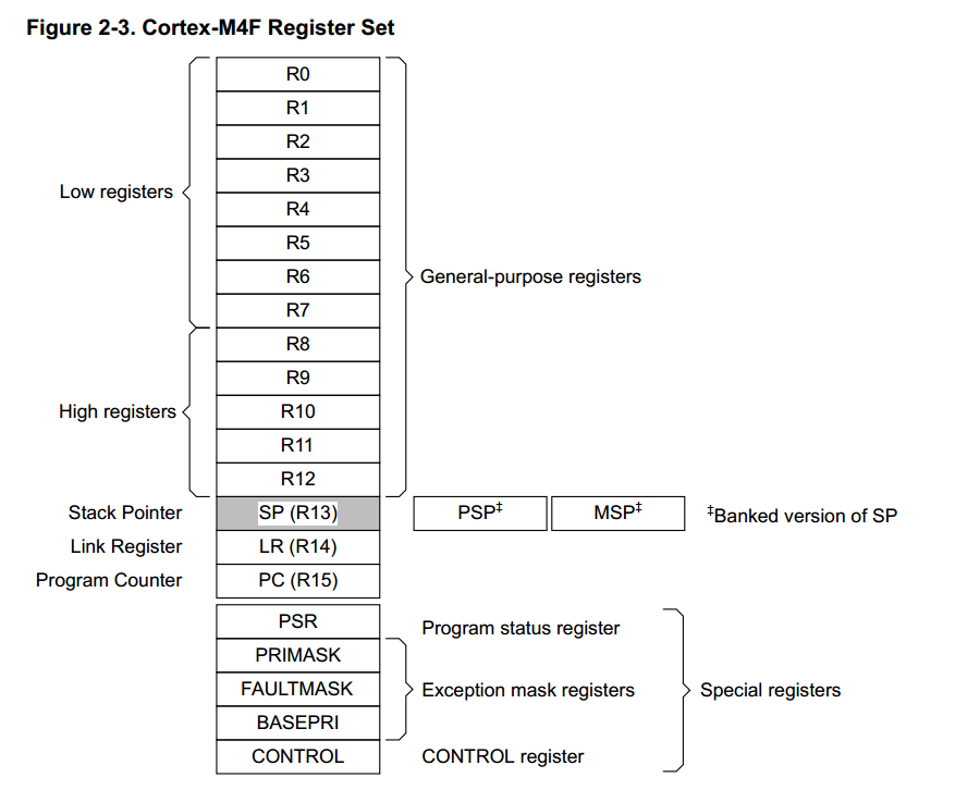
- Cortex-M4F register set
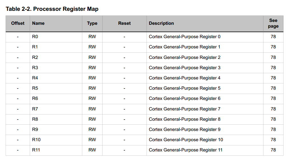
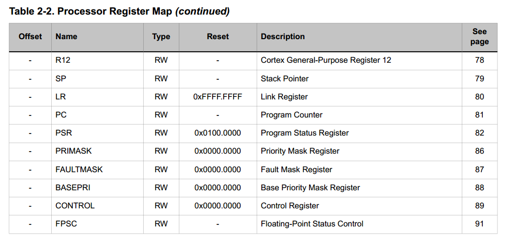
- Processor Register Map
Register Descriptions
Register 14: Stack Pointer (SP)
- Contain address of stack pointer.
-
In Thread mode, the function of this register changes depending on the ASP bit in the Control Register (CONTROL) register.
- When the ASP bit is clear, this register is the Main Stack Pointer (MSP).
- When the ASP bit is set, this register is the Process Stack Pointer (PSP).
- On reset, the ASP bit is clear, and the processor loads the MSP with the value from address 0x0000.0000.
- The MSP can only be accessed in privileged mode
- the PSP can be accessed in either privileged or unprivileged mode.
Register 15: Link Register (LR)
- Stores the return information for subroutines, function calls, and exceptions.
- The Link Register can be accessed from either privileged or unprivileged mode.
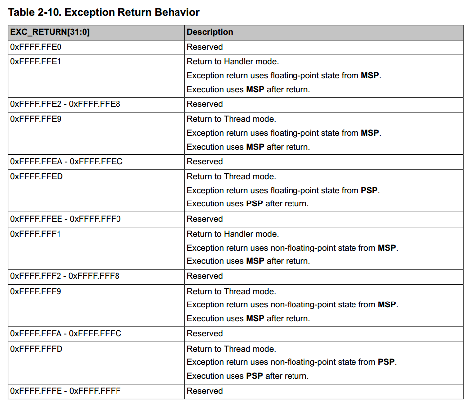
- EXC_RETURN[31:0] is loaded into the LR on exception entry.
Register 16: Program Counter (PC)
- Contains the current program address. On reset, the processor loads the PC with the value of reset vector, which is at address 0x0000.0004.
- Bit 0 of the reset vector is loaded into the THUMB bit of the EPSR at reset and must be 1.
- The PC register can be accessed in either privileged or unprivileged mode.
Register 17: Program Status Register (PSR)
Note: This register is also referred to as xPSR.
The Program Status Register (PSR) has three functions, and the register bits are assigned to the different functions:
- Application Program Status Register (APSR), bits 31:27, bits 19:16
- Execution Program Status Register (EPSR), bits 26:24, 15:10
- Interrupt Program Status Register (IPSR), bits 7:0
The PSR, IPSR, and EPSR registers can only be accessed in privileged mode; the APSR register can be accessed in either privileged or unprivileged mode
APSR contains the current state of the condition flags from previous instruction executions.
Memory Model
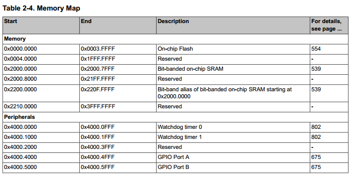
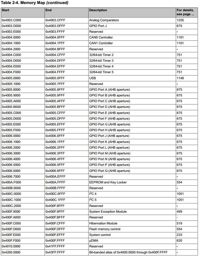
The processor has a fixed memory map that provides up to 4 GB of addressable memory.


Memory Regions, Types and Attributes
The memory map and the programming of the MPU split the memory map into regions. Each region has a defined memory type, and some regions have additional memory attributes. The memory type and attributes determine the behavior of accesses to the region
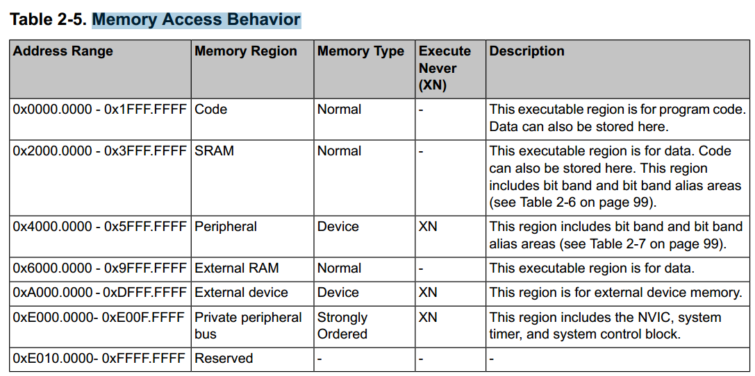
Note The Code, SRAM, and external RAM regions can hold programs. However, it is recommended that programs always use the Code region because the Cortex-M4F has separate buses that can perform instruction fetches and data accesses simultaneously.
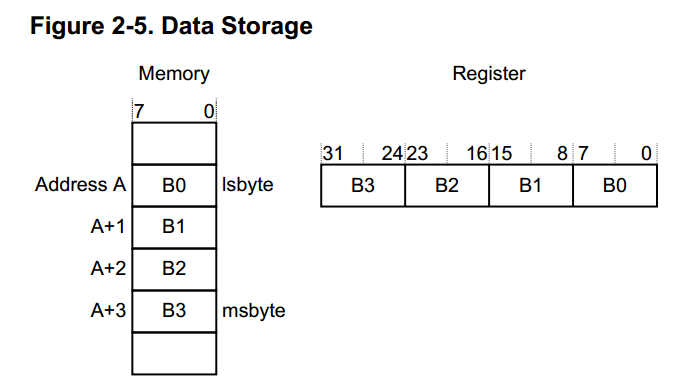
Data Storage
Data is stored in little-endian format
Exception Model
The ARM Cortex-M4F processor and the Nested Vectored Interrupt Controller (NVIC) prioritize and handle all exceptions in Handler Mode
The processor state is automatically stored to the stack on an exception and automatically restored from the stack at the end of the Interrupt Service Routine (ISR).
The vector is fetched in parallel to the state saving, enabling efficient interrupt entry. The processor supports tail-chaining, which enables back-to-back interrupts to be performed without the overhead of state saving and restoration.
Priorities on the system handlers are set with the NVIC System Handler Priority n (SYSPRIn) registers
Interrupts are enabled through the NVIC Interrupt Set Enable n (ENn) register and prioritized with the NVIC Interrupt Priority n (PRIn) registers
Priorities can be grouped by splitting priority levels into preemption priorities and subpriorities. All the interrupt registers are described in “Nested Vectored Interrupt Controller (NVIC)” on page 126.
Internally, the highest user-programmable priority (0) is treated as fourth priority, after a Reset, Non-Maskable Interrupt (NMI), and a Hard Fault, in that order. Note that 0 is the default priority for all the programmable priorities.
Important: After a write to clear an interrupt source, it may take several processor cycles for the NVIC to see the interrupt source deassert. Thus if the interrupt clear is done as the last action in an interrupt handler, it is possible for the interrupt handler to complete while the NVIC sees the interrupt as still asserted, causing the interrupt handler to be re-entered errantly. This situation can be avoided by either clearing the interrupt source at the beginning of the interrupt handler or by performing a read or write after the write to clear the interrupt source (and flush the write buffer).
Exception States
- Inactive. The exception is not active and not pending.
- Pending. The exception is waiting to be serviced by the processor. An interrupt request from a peripheral or from software can change the state of the corresponding interrupt to pending.
- Active. An exception that is being serviced by the processor but has not completed.
Note: An exception handler can interrupt the execution of another exception handler. In this case, both exceptions are in the active state.
- Active and Pending. The exception is being serviced by the processor, and there is a pending exception from the same source.
Exception Types
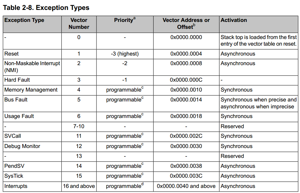
- Reset. Reset is invoked on power up or a warm reset. The exception model treats reset as a special form of exception. When reset is asserted, the operation of the processor stops, potentially at any point in an instruction. When reset is deasserted, execution restarts from the address provided by the reset entry in the vector table. Execution restarts as privileged execution in Thread mode.
- NMI. A non-maskable Interrupt (NMI) can be signaled using the NMI signal or triggered by software using the Interrupt Control and State (INTCTRL) register. This exception has the highest priority other than reset. NMI is permanently enabled and has a fixed priority of -2. NMIs cannot be masked or prevented from activation by any other exception or preempted by any exception other than reset.
- Hard Fault. A hard fault is an exception that occurs because of an error during exception processing, or because an exception cannot be managed by any other exception mechanism. Hard faults have a fixed priority of -1, meaning they have higher priority than any exception with configurable priority.
- Memory Management Fault. A memory management fault is an exception that occurs because of a memory protection related fault, including access violation and no match. The MPU or the fixed memory protection constraints determine this fault, for both instruction and data memory transactions. This fault is used to abort instruction accesses to Execute Never (XN) memory regions, even if the MPU is disabled.
- Bus Fault. A bus fault is an exception that occurs because of a memory-related fault for an instruction or data memory transaction such as a prefetch fault or a memory access fault. This fault can be enabled or disabled.
- Usage Fault. A usage fault is an exception that occurs because of a fault related to instruction execution, such as:
- An undefined instruction
- An illegal unaligned access
- Invalid state on instruction execution
- An error on exception return An unaligned address on a word or halfword memory access or division by zero can cause a usage fault when the core is properly configured.
- SVCall. A supervisor call (SVC) is an exception that is triggered by the SVC instruction.
In an OS environment, applications can use SVC instructions to access OS kernel functions and device drivers.
-
Debug Monitor. This exception is caused by the debug monitor (when not halting). This exception is only active when enabled. This exception does not activate if it is a lower priority than the current activation.
-
PendSV. PendSV is a pendable, interrupt-driven request for system-level service.
In an OS environment, use PendSV for context switching when no other exception is active. PendSV is triggered using the Interrupt Control and State (INTCTRL) register.
- SysTick. A SysTick exception is an exception that the system timer generates when it reaches zero when it is enabled to generate an interrupt. Software can also generate a SysTick exception using the Interrupt Control and State (INTCTRL) register.
In an OS environment, the processor can use this exception as system tick.
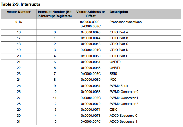
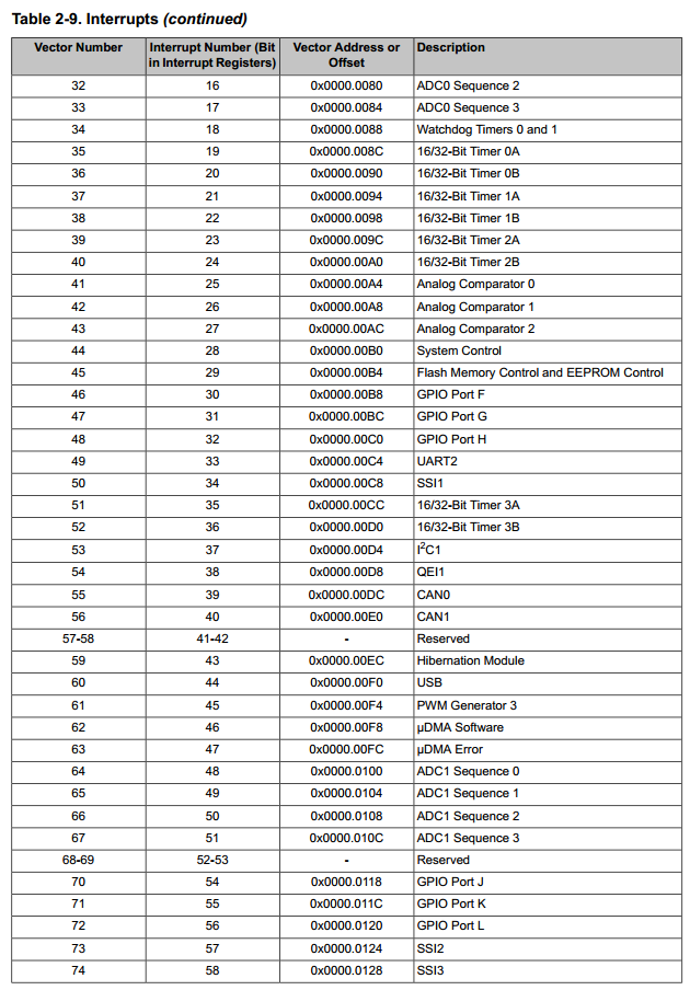
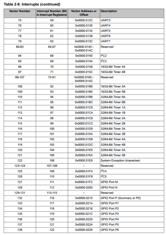
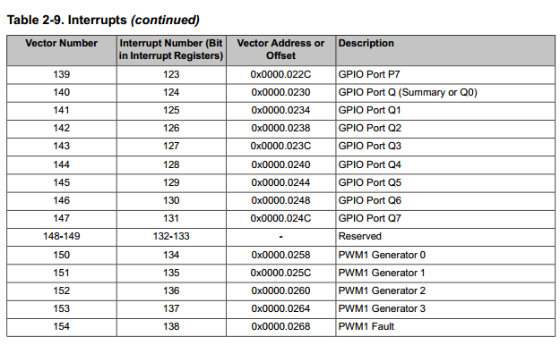
- Interrupt (IRQ). An interrupt, or IRQ, is an exception signaled by a peripheral or generated by a software request and fed through the NVIC (prioritized). All interrupts are asynchronous to instruction execution.
In the system, peripherals use interrupts to communicate with the processor. Table 2-9 lists the interrupts on the TM4C123GH6ZRB controller.
Exception Handlers
The processor handles exceptions using:
- Interrupt Service Routines (ISRs). Interrupts (IRQx) are the exceptions handled by ISRs.
- Fault Handlers. Hard fault, memory management fault, usage fault, and bus fault are fault exceptions handled by the fault handlers.
- System Handlers. NMI, PendSV, SVCall, SysTick, and the fault exceptions are all system exceptions that are handled by system handlers.
Vector Table
The vector table contains the reset value of the stack pointer and the start addresses, also called exception vectors, for all exception handlers
The vector table is constructed using the vector address or offset shown in Exception Table 2-8
- Order of the exception vectors in the vector table. . The least-significant bit of each vector must be 1, indicating that the exception handler is Thumb code

Note On system reset, the vector table is fixed at address 0x0000.0000. Privileged software can write to the Vector Table Offset (VTABLE) register to relocate the vector table start address to a different memory location, in the range 0x0000.0400 to 0x3FFF.FC00 (see “Vector Table” on page 108). Note that when configuring the VTABLE register, the offset must be aligned on a 1024-byte boundary.
lbr sp, =0xAAAA_BBBB
Exception Priorities
If multiple pending exceptions have the same priority, the pending exception with the lowest exception number takes precedence. For example, if both IRQ[0] and IRQ[1] are pending and have the same priority, then IRQ[0] is processed before IRQ[1].
When the processor is executing an exception handler, the exception handler is preempted if a higher priority exception occurs
When the processor is executing an exception handler, the exception handler is preempted if a higher priority exception occurs. If an exception occurs with the same priority as the exception being handled, the handler is not preempted, irrespective of the exception number. However, the status of the new interrupt changes to pending
Exception Entry and Return
Descriptions of exception handling use the following terms:
- Preemption. When the processor is executing an exception handler, an exception can preempt the exception handler if its priority is higher than the priority of the exception being handled. See “Interrupt Priority Grouping” on page 110 for more information about preemption by an interrupt. When one exception preempts another, the exceptions are called nested exceptions. See “Exception Entry” on page 111 more information.
- Return. Return occurs when the exception handler is completed, and there is no pending exception with sufficient priority to be serviced and the completed exception handler was not handling a late-arriving exception. The processor pops the stack and restores the processor state to the state it had before the interrupt occurred. See “Exception Return” on page 112 for more information.
- Tail-Chaining. This mechanism speeds up exception servicing. On completion of an exception handler, if there is a pending exception that meets the requirements for exception entry, the stack pop is skipped and control transfers to the new exception handler.
- Late-Arriving. This mechanism speeds up preemption. If a higher priority exception occurs during state saving for a previous exception, the processor switches to handle the higher priority exception and initiates the vector fetch for that exception. State saving is not affected by late arrival because the state saved is the same for both exceptions. Therefore, the state saving continues uninterrupted. The processor can accept a late arriving exception until the first instruction of the exception handler of the original exception enters the execute stage of the processor. On return from the exception handler of the late-arriving exception, the normal tail-chaining rules apply.
Exception Entry
-
Exception entry occurs when there is a pending exception with sufficient priority and either the processor is in Thread mode or the new exception is of higher priority than the exception being handled, in which case the new exception preempts the original exception.
- When one exception preempts another, the exceptions are nested.
- When the processor takes an exception, unless the exception is a tail-chained or a late-arriving exception, the processor pushes information onto the current stack. This operation is referred to as stacking and the structure of eight data words is referred to as stack frame
Note: stack frame is use to store a bundle of processor’s registers
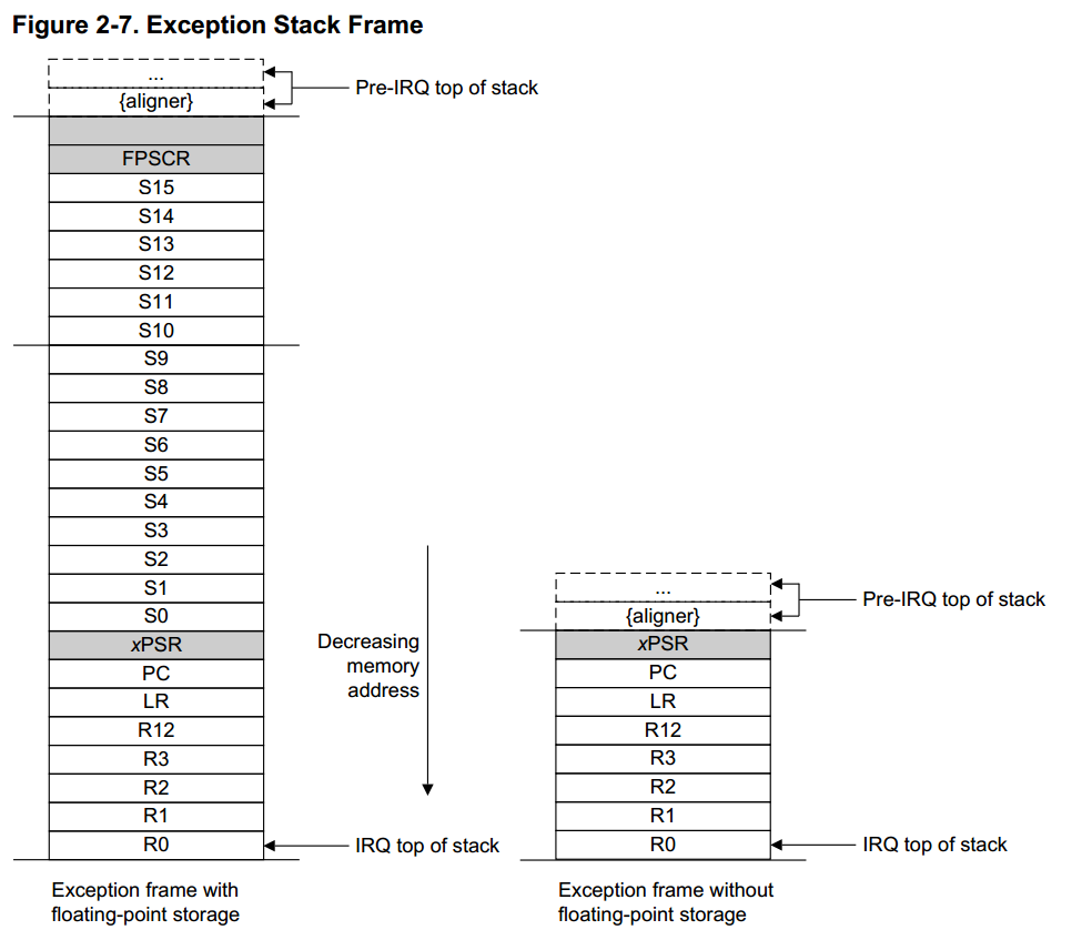
When using floating-point routines, the Cortex-M4F processor automatically stacks the architected floating-point state on exception entry
- Immediately after stacking, the stack pointer indicates the lowest address in the stack frame.
- The stack frame includes the return address, which is the address of the next instruction in the interrupted program. This value is restored to the PC at exception return so that the interrupted program resumes.
- In parallel with the stacking operation, the processor performs a vector fetch that reads the exception handler start address from the vector table. When stacking is complete, the processor starts executing the exception handler. At the same time, the processor writes an EXC_RETURN value to the LR, indicating which stack pointer corresponds to the stack frame and what operation mode the processor was in before the entry occurred.
- If no higher-priority exception occurs during exception entry, the processor starts executing the exception handler and automatically changes the status of the corresponding pending interrupt to active.
- If another higher-priority exception occurs during exception entry, known as late arrival, the processor starts executing the exception handler for this exception and does not change the pending status of the earlier exception.