A WS2812 ring from Android 7 over spidev, and why it flickered
Situation
After two weeks of bare metal I wanted to see the board’s own Android once, and I had a few 16-LED WS2812 rings lying around. WS2812s need tight bit timing (a few hundred ns per pulse), Android gives a normal app no access to hardware, and the S5P4418 has no LED peripheral. The usual trick is SPI: send bytes whose bit patterns look like WS2812 pulses on MOSI.
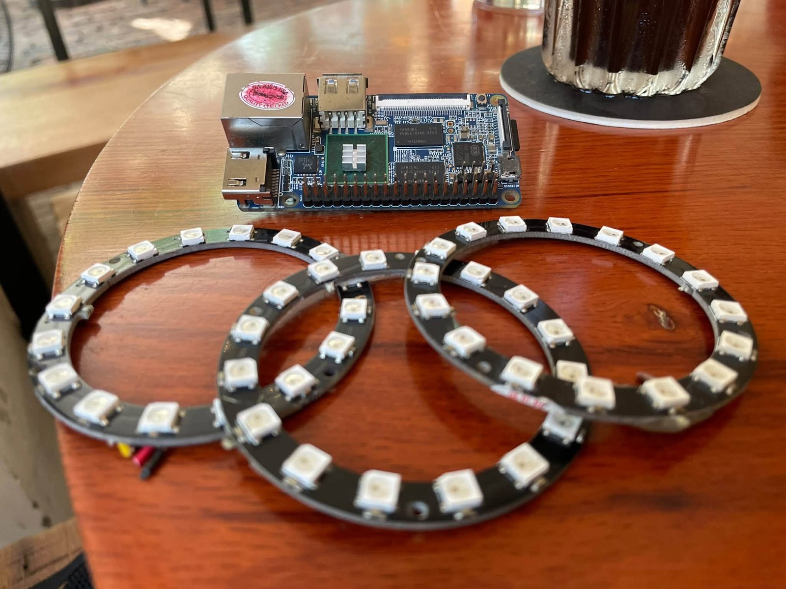
Where it started: the board and three 16-LED rings on a café table, nothing wired yet.
Task
Put Android on a microSD card and boot it. Drive the ring from Android through /dev/spidev0.0,
smoothly. And write a small app for the HDMI screen to pick effects, with the ring drawn live.
Action
Android 7.1.2 on a card
FriendlyELEC doesn’t publish one Android .img any more, only parts plus a partition map, so I wrote
android_sd.sh: fetch clones their sd-fuse_s5p4418, downloads the current image (282 MB), checks
its sha256; fuse refuses to run without CONFIRM=<device> and won’t touch a non-removable disk, then
runs their own fusing.sh. Writing the card took 4 min 33 s.
It booted: Android 7.1.2 (API 25), launcher at 1280×720, about 61 s from power to picture on the first
boot. One gotcha: /data was 4.44 GiB on an 11.82 GiB partition. fusing.sh runs resize2fs for
FriendlyCore and friends, but for android7 it only does echo "". Fix is an e2fsck + resize2fs
with the card in a PC.
Wiring
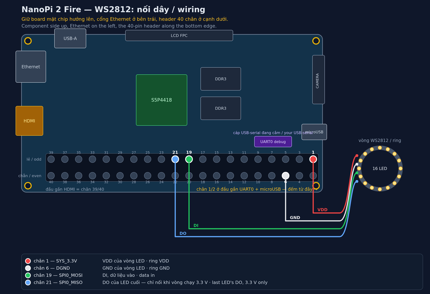
First attempt: nothing lit. The board side was right (GPIOC31 muxed to SPI0). I’m fairly sure I’d counted pins from the wrong end of the header: from the HDMI end, “pin 1” is pin 39, a ground. I drew this picture from the silkscreen on the board’s underside, and after that all 16 LEDs came up red.
I also wired the last LED’s DO back to MISO, so the program can read back what the ring passes on.
Timing that didn’t match the request
No requested SPI clock gave bit times inside the WS2812 windows. Instead of modelling it I measured: each ioctl costs ~100 µs, and the rest scales with length at a fixed fraction of the requested rate: 0.835 with 8-bit words, 0.907 with 16-bit. Both fit one number: the controller leaves an idle gap of 1.5 clocks after every word. So I made one LED bit exactly one SPI word and checked the period with the gap included.
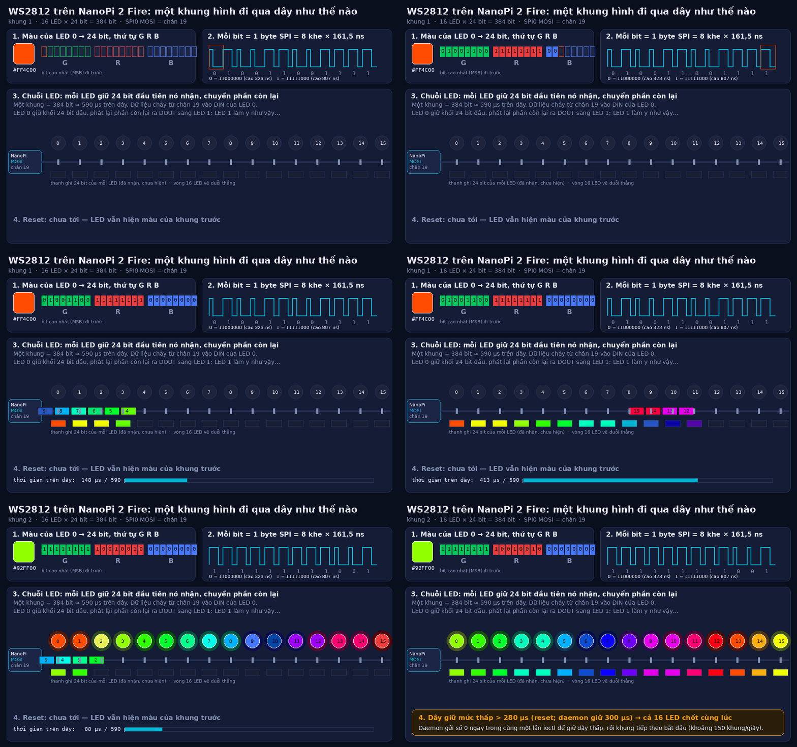
One frame on the wire, 13 s loop. In this drawing each LED bit is one SPI byte (8 slots × 161.5 ns), 384 bits for the ring, each LED keeps the first 24 and passes the rest on, then the line stays low past 280 µs and all 16 latch. (Vietnamese labels.)
The readback said the ring wasn’t a classic WS2812B: its 1s came back at 482 ns and 0s at 321 ns, which is the WS2812B-V5’s timing (with a longer reset). New threshold, driven reset: probe 16/16, verify 480/480.
The flicker
Colours were right, but the ring flickered. What I ruled out, with measurements:
| Suspect | Test | Verdict |
|---|---|---|
| current | 113 mA static, steady; every frame 75–76 mA | no |
| latch time | 300 µs and 2000 µs flicker the same | no |
| slow frames | render ≤ 28 µs per frame | no |
| line idle level between frames | hold MOSI low for the whole gap | gone |
My solid-colour tests could never have shown it: a frame that slid by a few bits is the same frame
when every pixel is equal. Twice I also tested while an old animation was still running, so two
processes interleaved frames on one device node. The port takes an exclusive flock now.
The app
SELinux blocks an app from opening spidev even with mode 0666, and su only works for the shell. So
the native program became a root daemon on 127.0.0.1:5812 and the app is a client that sends text
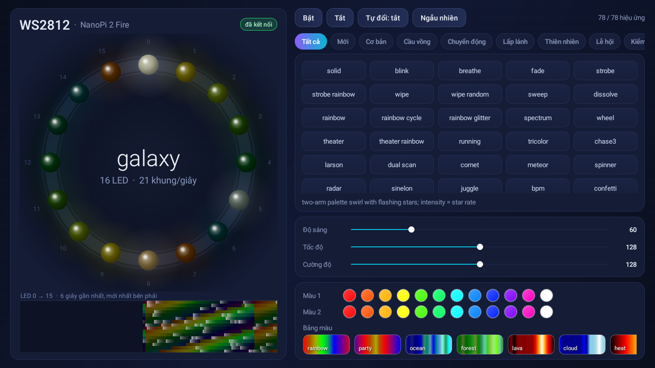
commands. The on-screen ring is the real frame: the app asks for px about 21 times a second
(measured) and draws each LED.
No Android Studio, no Gradle: build-tools 30.0.3 and platform 25 downloaded into a folder in my home,
then aapt2 → Eclipse’s Java compiler (the javac on that PC was a broken wrapper) → d8 (which also
desugars the lambdas API 25 doesn’t have) → zipalign → apksigner. The APK is 33 KB. 78 effects,
eight of them written for this ring.
Result
The 16-LED WS2812B-V5 ring runs every effect smoothly from Android, probe 16/16 and readback 480/480 bytes clean. Frames go out at ~190–208 Hz, and the default spidev buffer fits up to 170 RGB LEDs per ioctl. The 33 KB app ran on the board, and a tap on the screen changed the real ring.
A week later the same green-flickering LED 0 came back in my bare-metal driver for the webcam firmware. Same cause: the PL022 lets go of the TX line when it isn’t sending, so it floated high between frames and LED 0 read the first bit (the top bit of green) as a 1. Driving the line low over the gap fixed it there too.
What I’d do next
The board reset once right after installing the app, and I don’t know why. My guess is the 5 V supply (board, screen and ring on one adapter, during the heaviest load Android puts on it), but I didn’t measure it. The ring should get its own supply. The daemon also doesn’t start at boot yet.