A WS2812 ring on the RISC-V MCU hidden inside the RK3568
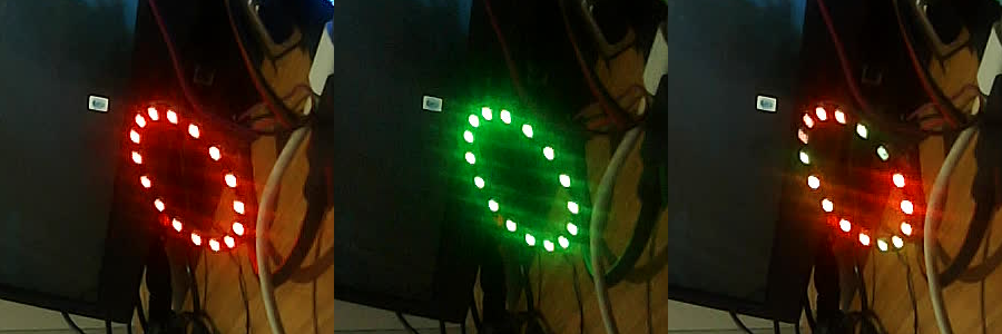
Crops from the webcam on my desk: fill red (16/16), fill green (16/16), and the rainbow effect, where the blue part stays dark.
Situation
Easy to miss in the spec sheet: the RK3568 has a small RISC-V core of its own next to the four A55s, an SCR1, RV32IMC, at 148.5 MHz under Android. I’d driven a 16-LED WS2812B ring before, on the NanoPi 2 Fire and on core 3 of this board. With Android 14 on the A55s now, I wanted the LEDs owned by something that doesn’t care what Android is doing.
Task
FreeRTOS on the MCU, driving the ring on header pin 19 (SPI3_MOSI_M1), with the ring’s DO wired back
to pin 21 so the MCU can check what came out. The A55 side only sends commands, and my NanoPi phone app
(vn.np2f.ws2812) should work unchanged. Plus a hook for music: beats and energy from Android to the
MCU, for effects that follow a song.
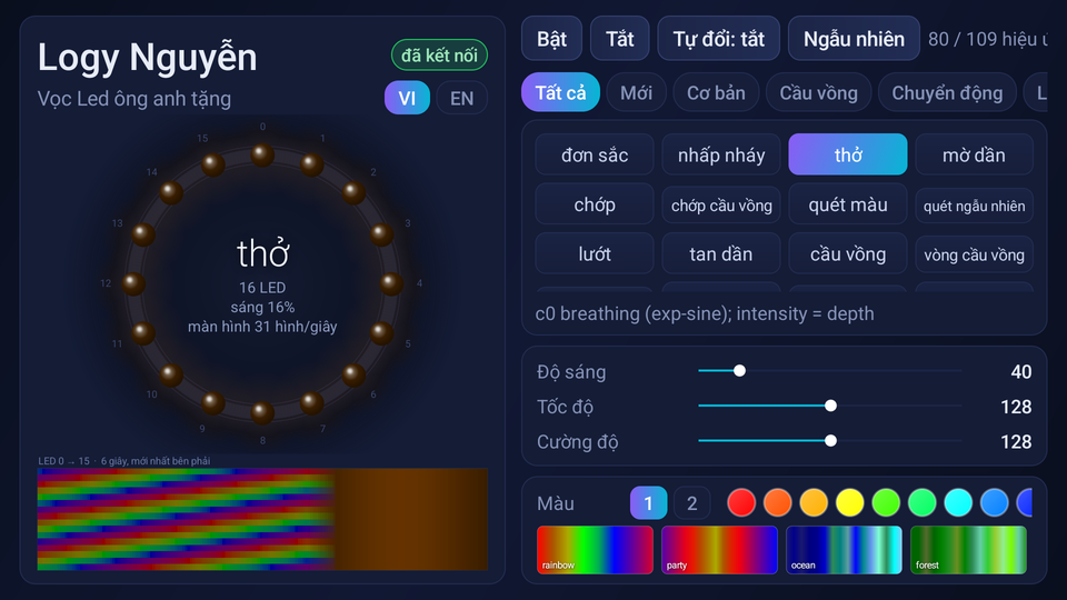
The phone app I’d written for the NanoPi 2 Fire, pointed at the ROCK 3A: 16 LEDs on a ring, “thở” (breathe) selected, the effect list filtered to 80 of 109. It talks to r3a_ringd on the board without knowing an MCU is behind it.
Action
The firmware was the easy half. The MCU sends each LED bit as a pattern of SPI bits, with interrupts
off during the frame and a resend if a frame got a gap. A ring task renders the effects (78 of them, in
soft-float) and runs commands between frames. On Android a bridge, r3a_ringd, speaks the NanoPi
daemon’s text protocol on 127.0.0.1:5812 and writes into a shared DRAM window plus a mailbox doorbell.
The kernel side: SPI3 disabled in the DTS (the MCU owns it) and a 2 MiB no-map region for the MCU.
It all worked, in the sense that every register read back right, the frames came out at 50 fps, and pin 19 toggled 35 529 edges per second. The ring stayed completely dark.
My first guess was dead LEDs, so I built an MCU image that just tests them (bit-bang, wire, rgbw). Then I hooked a Saleae up to DI and DO and measured. I was sure the wiring was right. The Saleae said DI was flat. It turned out to be four separate faults stacked on top of each other, and each one hid the next:
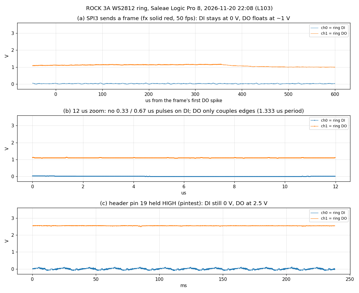
The capture that ended my “dead LEDs” theory (Saleae Logic Pro 8, 2026-11-20 22:08): the MCU sends solid-red frames at 50 fps and DI (blue) sits at 0 V, even with pin 19 held high. Fault 1, an open wire.
| # | What I saw | Cause | Fix |
|---|---|---|---|
| 1 | DI flat on the analyzer | the DI wire was open | rewired |
| 2 | DI low only fell to 1.39 to 1.67 V | the second ring board pulls DI up through ~1.3 kΩ, against my 300 to 470 Ω series resistor | bypassed the resistor, pin 19 drive strength from 0x03 to 0x3f |
| 3 | still dark with the ring on 5 V | pin 19’s high is 3.39 to 3.51 V, below the 3.5 V VIH at 5 V | ring VDD on 3.3 V (header pin 1) |
| 4 | still dark at 3.3 V | my bit timing: a 1 was 667 ns high | NanoPi timing: SPI3 at 6 MHz, 8 slots per bit, 0 = 333 ns, 1 = 833 ns, reset 800 µs |
After the fourth one, just before midnight, all 16 LEDs went red. Then I lit one byte at a time and photographed it to settle the order: byte 0 is LED 0 green, byte 1 is LED 0 red, byte 3 is LED 1 green. Standard WS2812B GRB, 24 bits per LED.
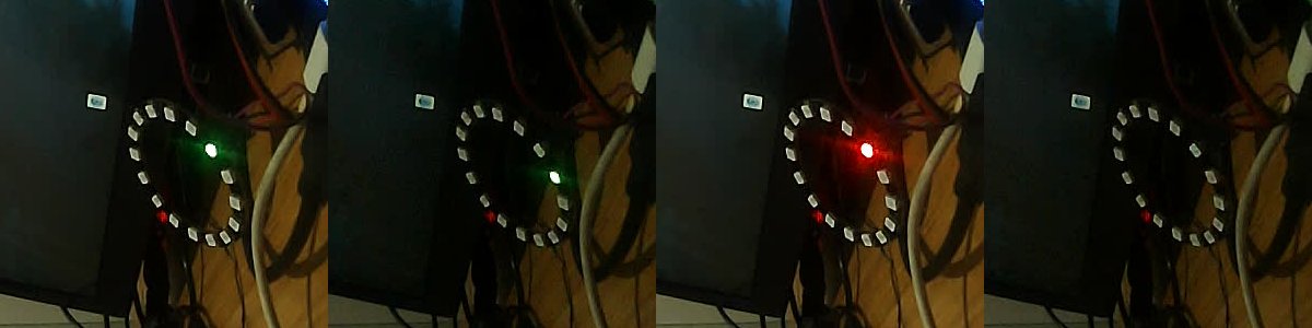
Lighting one byte at a time: byte 0 gives LED 0 green, byte 1 LED 0 red, and so on. That’s how I settled GRB rather than guessing.
One trap I set for myself along the way: loading a new MCU image with mcuctl load while r3a_ringd
was running left the MCU unable to start any image, the vendor one included, until a full board reboot.
Now I only load through the init service.
rock3a# r3a_ringd send mcu
core 148.499 MHz (mcycle over TIMER5), uptime 13940341 ms, free heap 12832 bytes
SPI3 VERSION 0x00110002, TX FIFO 64 entries, BAUDR 8, CTRLR0 0x00040402, set-up ok
…
mode 1, pin toggles 0, frames 621169, underruns 9, gaps 7, resent 7, stuck 0, wire 523 us, render 148 us, period 20046 us
BAUDR 8 is the old 3 MHz setting (24 MHz / 8). Nine underruns and seven resent frames in 621 169
frames: the MCU side was never the problem.
Result
The ring lights: 16/16 red and green, driven by the MCU while Android runs, at 50.00 frames/s and 523 to 525 µs per frame on the wire. On the analyzer: 332 / 834 / 1 334 ns for 0-high / 1-high / bit period, 384 bits = 16 pixels.
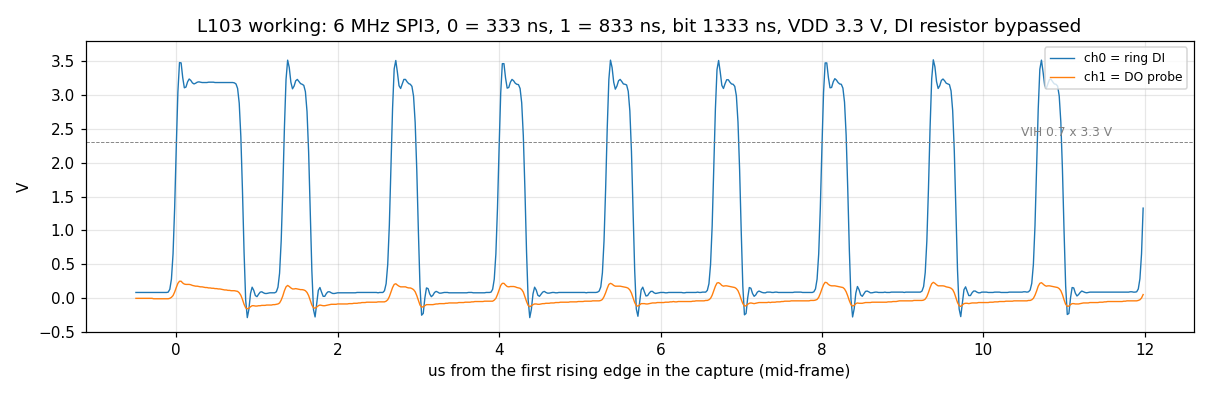
The waveform once it worked: SPI3 at 6 MHz, 0 = 333 ns high, 1 = 833 ns, bit period 1333 ns, DI swinging to 3.4 V with the resistor bypassed and the ring on 3.3 V.
The 78 effects render on the MCU in 259 µs per frame on average, worst 990 µs (bounce). The NanoPi app works unchanged: tapping “thở” (breathe) made the MCU report effect 2 running. The music hook carries 100.0 audio blocks/s from Android with a 777 µs average round trip.
What I’d do next
At 3.3 V blue never lights, and with red on, green gets weak, so yellow and white look red. I think that’s the LEDs’ forward voltage, not the data (green needs ~3 V, blue ~3.1 V plus the driver drop). For full colour I’ll try a 74AHCT125 level shifter with the ring on 5 V, or the ring on 5 V through a diode (~4.3 V). Neither tested yet. The first ring (a WS2812B-V5) only ever got the old timing at 5 V, so I still don’t know if it’s dead.